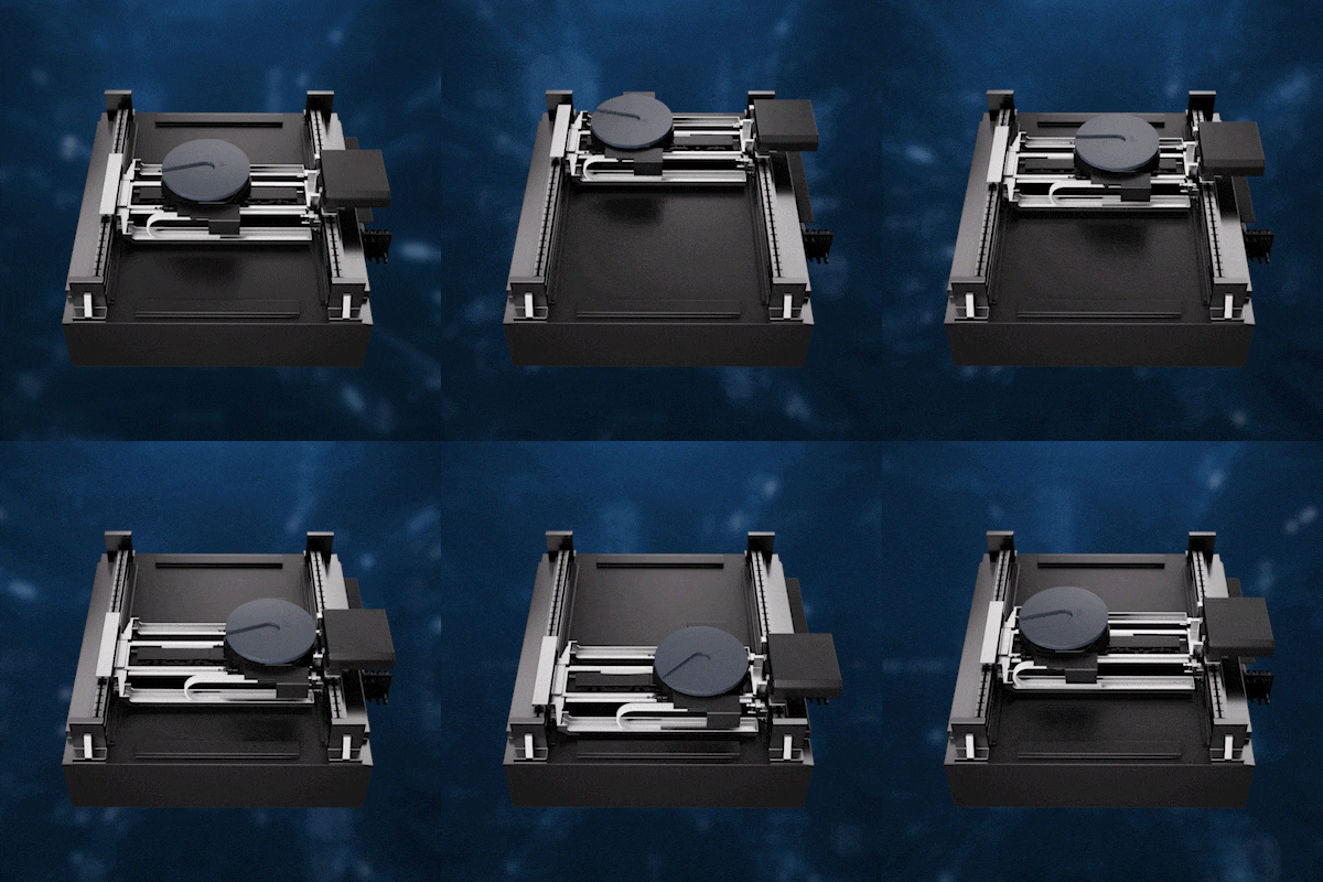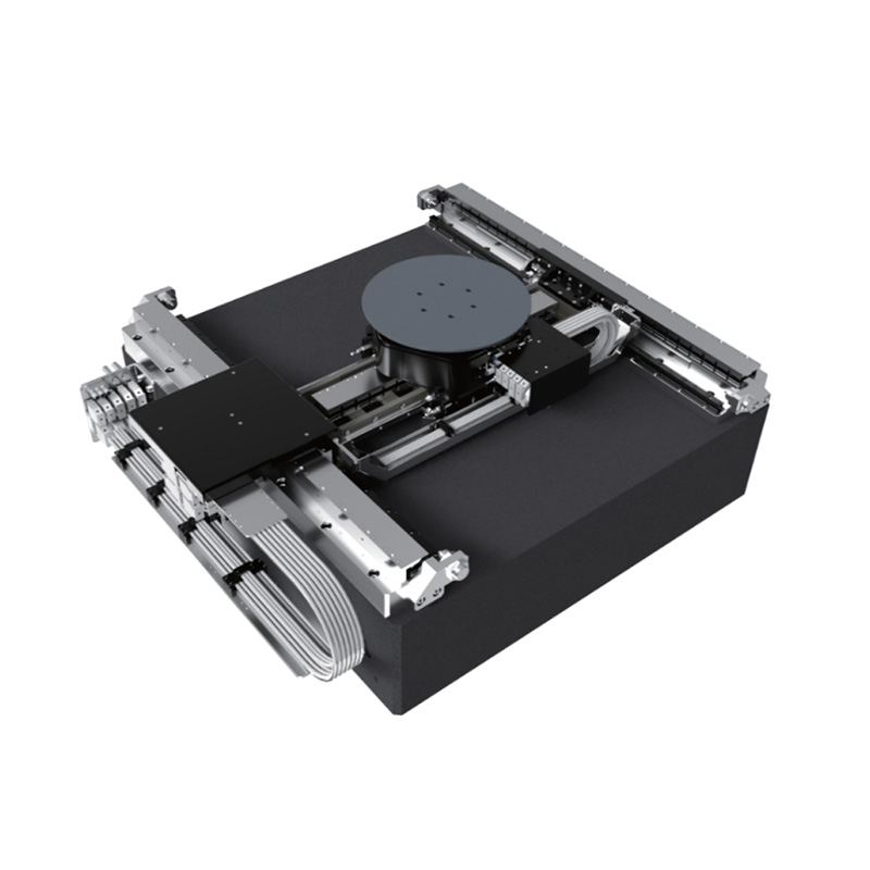


The stage is composite of two-dimensional mechanical guide and air bearing guide, has the advantages of both mechanical guide and air bearing guide. The high stiffness of the mechanical guide in the XY plane withstands high accelerations and provides high bi-directional repeatability, while the air bearing ensures excellent dynamic flatness over the full travel.
The stage adopts modularization, orthogonality design to integrate MZT standard module on XYY horizontal H-type motion module for high accuracy, high stiffness linear motion and rotary motion in X, Z, T axes with 4 degrees of freedom.
The MZT uses the large-stroke maglev gravity compensation technology, which has the function of reducing the load of the vertical motor and greatly improving the vertical motion performance and lifetime.
The XY horizontal H-type motion module adopts aligned design between centers of gravity and motor forces as well as lightweight design techniques which reduce the eccentric heart impact on high-precision mechanical guide and improve the reliability and life of motion systems, as well as enable to bias correction for slightly panning Y1 and Y2 motors.
The platform can also be integrated on top of an active damping system module to further improve system performance.

*Interface dimensions from HS1000
|
|
HS1000-00 |
|||
|
Axes name |
X |
Y1/Y2 |
Z |
T |
|
Travel range |
320 mm |
550 mm |
10 mm |
360 °, Infinite |
|
Max. velocity |
1.2 m/s |
1.2 m/s |
0.1 m/s |
900 °/s |
|
Max. acceleration |
12 m/s² |
12 m/s² |
2 m/s² |
6280 °/s² |
|
Accuracy_indicative value |
±10 μm |
±10 μm |
NA |
±30 arcsec |
|
Accuracy_calibration value |
±1 μm |
±1 μm |
±0.5 μm/1 mm |
±3 arcsec |
|
Bidirectional repeatability |
±0.4 μm |
±0.4 μm |
±0.3 μm/1 mm |
±2 arcsec |
|
Position stability (3σ)* |
±25 nm* |
±25 nm* |
±15 nm* |
±0.2 arcsec |
|
Straightness |
±2 μm over range |
±1.5 μm over range |
2 μm |
NA |
|
Axial runout |
NA |
NA |
NA |
±1.5 μm |
|
Radial runout |
NA |
NA |
NA |
±1.5 μm |
| Mechanical properties | ||||
|
Moving mass(without payload) |
15 Kg |
30 Kg |
5.5 Kg |
NA |
|
Max. load |
2 Kg (customizable) |
|||
|
Stage mass |
666 Kg |
|||
|
Dimensions |
1040 mm×1050 mm×405.3 mm (size between Chuck adsorption surface and marble:157.8 mm) |
|||
*Technical data specified with 8μm pitch encoder.
The series is configured with options that can be selected based on the user's actual application. Options include encoders, shock absorber, control system, and more.
|
Table 1 Encoder Options |
|
|
-S1 |
Incremental analog optical linear encoder, 1Vpp, 20μm Pitch |
|
-S2 |
Incremental digital optical linear encoder, TTL, 20μm Pitch |
|
-S3 |
Absolute optical linear encoder, BISS, 20μm Pitch |