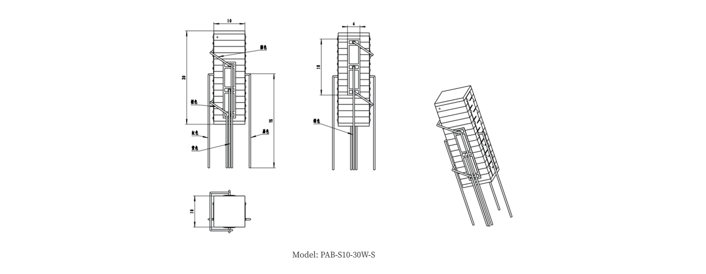
The stacked piezoelectric ceramic actuator adopts a structure formed by stacking piezoelectric ceramic plates. It achieves the superposition output of the displacement response of multiple ceramic layers under electrical signal excitation. It has a sub-millisecond response time and a maximum displacement exceeding 180μm.
|
|
Dimensions |
Displacement |
Stiffness |
Blocking force** |
Electrical capacitance |
Resonant frequency |
|
Unit |
mm×mm×mm |
μm |
N/μm |
N |
nF |
kHz |
|
Tolerance |
|
±15% |
|
Max. value |
±15% |
±15% |
|
PAB-S3-5 |
3×3×5 |
5 |
64 |
350 |
120 |
250 |
|
PAB-S3-9 |
3×3×9 |
9 |
38 |
350 |
250 |
150 |
|
PAB-S5-5 |
5×5×5 |
5 |
187 |
1000 |
350 |
250 |
|
PAB-S5-9 |
5×5×9 |
10 |
104 |
1000 |
680 |
140 |
|
PAB-S5-18 |
5×5×18 |
20 |
52 |
1000 |
1300 |
70 |
|
PAB-S5-20 |
5×5×20 |
20 |
43 |
1000 |
1600 |
60 |
|
PAB-S5-36 |
5×5×36 |
40 |
26 |
1000 |
2800 |
35 |
|
PAB-S5-45 |
5×5×45 |
50 |
21 |
1000 |
3800 |
27 |
|
PAB-S5-60 |
5×5×60 |
68 |
16 |
1000 |
5000 |
21 |
|
PAB-S5-72 |
5×5×72 |
80 |
13 |
1000 |
6000 |
17 |
|
PAB-S7-9 |
7×7×9 |
10 |
191 |
1960 |
1500 |
140 |
|
PAB-S7-18 |
7×7×18 |
20 |
86 |
1960 |
2700 |
70 |
|
PAB-S7-20 |
7×7×20 |
20 |
57 |
1960 |
3000 |
70 |
|
PAB-S7-36 |
7×7×36 |
40 |
48 |
1960 |
6000 |
34 |
|
PAB-S7M-36 |
7×7×36 |
40 |
48 |
1960 |
9500 |
35 |
|
PAB-S7-45 |
7×7×45 |
50 |
38 |
1960 |
9000 |
27 |
|
PAB-S7-54 |
7×7×54 |
60 |
32 |
1960 |
9500 |
23 |
|
PAB-S7-60 |
7×7×60 |
66 |
29 |
1960 |
11000 |
21 |
|
PAB-S7-72 |
7×7×72 |
75 |
24 |
1960 |
12000 |
18 |
|
PAB-S7-90 |
7×7×90 |
100 |
19 |
1960 |
16000 |
14 |
|
PAB-S10-18 |
10×10×18 |
20 |
185 |
3900 |
6000 |
70 |
|
PAB-S10-30 |
10×10×30 |
33 |
105 |
3900 |
10000 |
41 |
|
PAB-S10-36 |
10×10×36 |
40 |
85 |
3900 |
13000 |
34 |
The cross-sectional dimensions within ±0.1mm tolerance, and the length dimension within standard tolerance of ±0.1mm.
Tolerance can be reduced to ±10μm for special request
Displacement dimensions within ±15% tolerance
Optional soldering of standard wiring harness available, length 75mm, AWG32, PTFE insulation, followed by 'W' in the product code
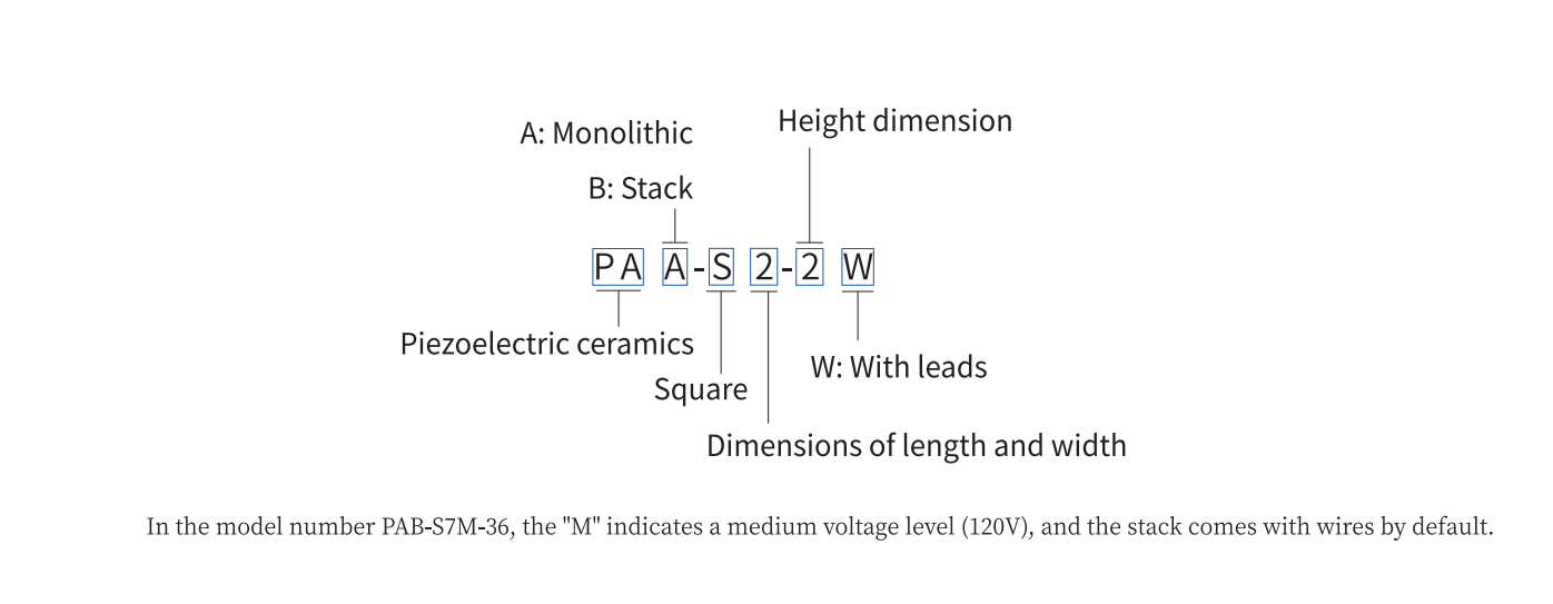
*Displacement test: drive voltage range 0 to 150V, another PAB - S7M - 36 drive voltage 0~120V, tolerance ±15%
**Blocking force test:The force that compresses the ceramic elongation to zero at a driving voltage of 150V
***Capacitance test conditions:ambient temperature environment, 1Vpp, 1kHz, tolerance ±15%
Other specifications can be customized on request
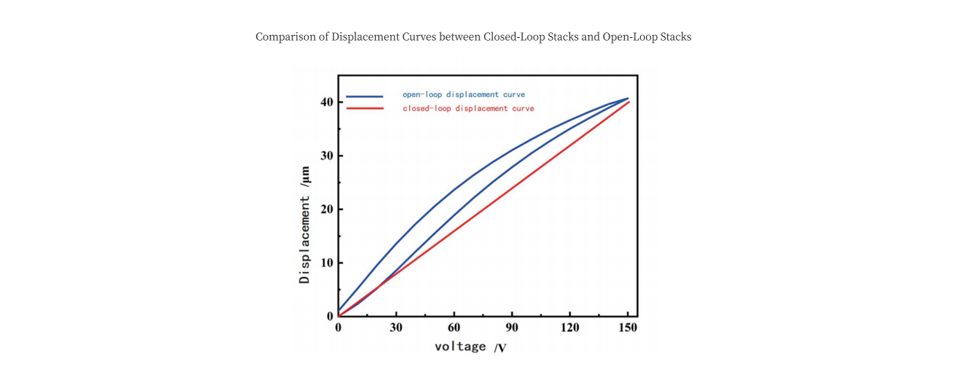
Closed-loop Version
|
|
PAB-S5-36W-S |
PAB-S7-36W-S |
PAB-S10-36W-S |
Unit |
Tolerance |
|
Active axes |
Z |
Z |
Z |
|
|
|
Operating voltage |
-20~150 |
-20~150 |
-20~150 |
V |
|
|
Max. displacement |
40 |
40 |
40 |
μm |
±15% |
|
Push force |
1000 |
1960 |
3900 |
N |
Max. value |
|
Electrical capacitance |
2.8 |
6 |
13 |
μF |
±15% |
|
Resonant frequency |
34 |
34 |
34 |
kHz |
±15% |
|
Strain gauge resistance |
350 |
350 |
350 |
Ω |
±3Ω |
|
Curie temperature |
230 |
230 |
230 |
°C |
|
|
Electrode |
Silver |
Silver |
Silver |
|
|
| Dimensions | |||||
|
A |
5 |
7 |
10 |
mm |
±0.1 mm |
|
B |
5 |
7 |
10 |
mm |
±0.1 mm |
|
H |
36 |
36 |
36 |
mm |
±0.1 mm |
*Displacement test: drive voltage range 0 to 150V, tolerance ±15%.
**Thrust test: drive voltage range 0 to 150V
***Capacitance Measurement Conditions: Room temperature environment, 1 Vpp, 1 kHz, tolerance ±15%.
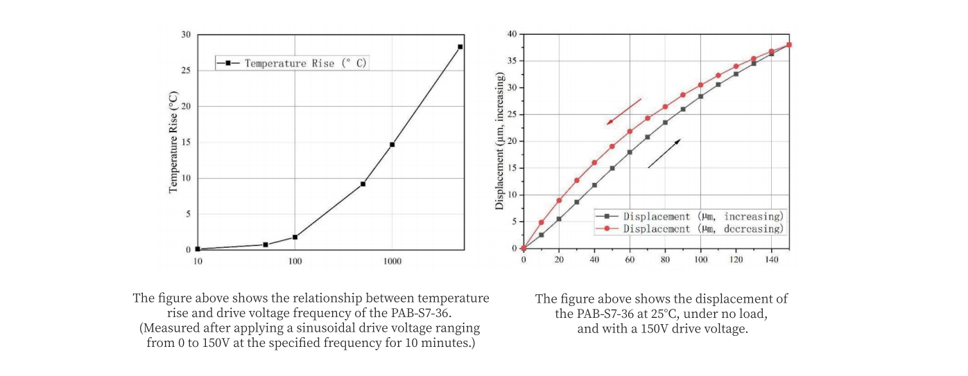
Performance Chart
Closed-loop Version
Performance Chart