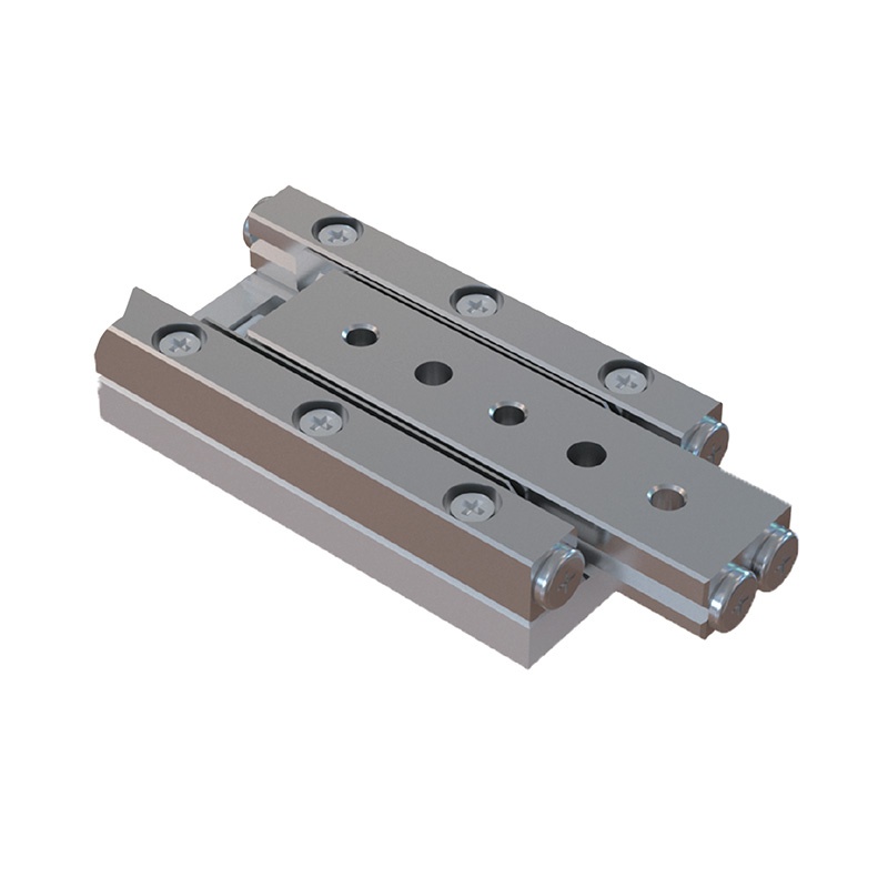
Piezoelectric Inertia Motor is a linear motion positioning device based on stick-slip drive logic, which can achieve millimeter-level motion stroke and nanometer-level positioning accuracy, with the advantages of small size, high stiffness and fast positioning, the motor integrates high-precision closed-loop sensors, which is very suitable for nano-micro displacement control systems.
|
|
PMIN-C24X-20A |
PMIN-C24X-30A |
Unit |
Tolerance |
|
Active Axes |
X |
X |
|
|
| Motion and positioning | ||||
|
Travel range |
20 |
30 |
mm |
|
|
Sensor |
Linear encoder |
Linear encoder |
|
|
|
Open loop resolution |
1 |
1 |
nm |
|
|
Sensor resolution |
40 |
40 |
nm |
|
|
Sensor signal |
AqB(Microstep box output) |
AqB(Microstep box output) |
|
|
|
Min. displacement |
- |
- |
nm |
Typical value |
|
Unidirectional repeatability |
500 |
500 |
nm |
Typical value |
|
Bidirectional repeatability |
800 |
1000 |
nm |
Typical value |
|
Pitch |
50 |
50 |
arcsec |
Typical value |
|
Yaw |
50 |
50 |
arcsec |
Typical value |
|
Closed loop velocity* |
10 |
10 |
mm/s |
Max. value |
| Mechanical Properties | ||||
|
Max. vertical load capacity |
30 |
30 |
N |
Max. value |
|
Guide type |
Cross roller guide |
|
|
|
|
Motor type |
Stick-slip inertial motor |
|
|
|
|
Drive force |
1.5 |
1.5 |
N |
Typical value |
|
Holding force |
2.0 |
2.0 |
N |
Min. value |
|
Operating voltage |
0 - 70 |
0 - 70 |
V |
|
| Miscellaneous | ||||
|
Operating temperature range |
0 - 50 |
0 - 50 |
°C |
|
|
Drive frequency range |
2k - 15k(Recommended Drive Frequency Range:5k - 7kHz) |
kHz |
|
|
|
Material |
Aluminum Alloy/Stainless Steel (Base defaults to Stainless Steel) |
|
|
|
|
Cable length |
2 |
2 |
m |
±0.02 m |
|
Motor interface |
Sub-D15 male connector |
Sub-D15 male connector |
|
|
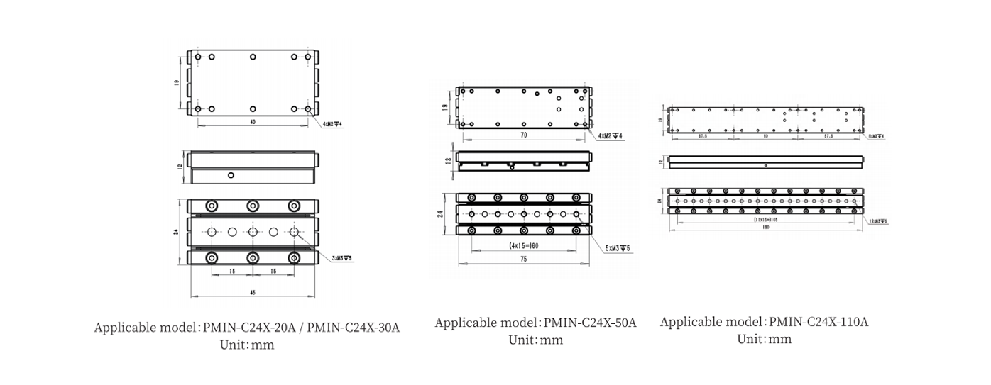
| Dimensions | ||||
|
A |
24 |
24 |
mm |
|
|
B |
11.5 |
11.5 |
mm |
|
|
L |
45 |
45 |
mm |
|
|
|
PMIN-C24X-50A |
PMIN-C24X-110A |
Unit |
Tolerance |
|
Active Axes |
X |
X |
|
|
| Motion and positioning | ||||
|
Travel range |
50 |
110 |
mm |
|
|
Sensor |
Linear encoder |
Linear encoder |
|
|
|
Open loop resolution |
1 |
1 |
nm |
|
|
Sensor resolution |
40 |
40 |
nm |
|
|
Sensor signal |
AqB(Microstep box output) |
AqB(Microstep box output) |
|
|
|
Min. displacement |
- |
- |
nm |
Typical value |
|
Unidirectional repeatability |
500 |
500 |
nm |
Typical value |
|
Bidirectional repeatability |
800 |
800 |
nm |
Typical value |
|
Pitch |
50 |
50 |
arcsec |
Typical value |
|
Yaw |
50 |
50 |
arcsec |
Typical value |
|
Closed loop velocity* |
10 |
10 |
mm/s |
Max. value |
| Mechanical Properties | ||||
|
Max. vertical load capacity |
30 |
30 |
N |
Max. value |
|
Guide type |
Cross roller guide |
|
|
|
| Drive Properties | ||||
|
Motor type |
Stick-slip inertial motor |
|
|
|
|
Drive force |
1.5 |
1.0 |
N |
Typical value |
|
Holding force |
2.0 |
1.5 |
N |
Min. value |
|
Operating voltage |
0 - 70 |
0 - 70 |
V |
|
| Miscellaneous | ||||
|
Operating temperature range |
0 - 50 |
0 - 50 |
°C |
|
|
Drive frequency range |
2k - 15k(Recommended Drive Frequency Range:5k - 7kHz) |
kHz |
|
|
|
Material |
Aluminum Alloy/Stainless Steel (Base defaults to Stainless Steel) |
|
|
|
|
Cable length |
2 |
2 |
m |
±0.02 m |
|
Motor interface |
Sub-D15 male connector |
Sub-D15 male connector |
|
|
| Dimensions | ||||
|
A |
24 |
24 |
mm |
|
|
B |
11.5 |
11.5 |
mm |
|
|
L |
75 |
180 |
mm |
|
*PMIN-C24X-50A models default to a stainless steel base. For lightweight requirements, an aluminum alloy version (-AL) is available.
-AL: Aluminum alloy base
* The actual operating speed depends on the power of the drive and control circuit.
* Maximum vertical load: 30N, provided that the center of gravity of the load is located at the center of the motor.
All specifications are based on room temperature conditions (22±3°C).
Usage Precautions:
1. The motor must be used in a clean indoor environment;
2. The motor must be used in conjunction with the drive and control unit provided by YG.
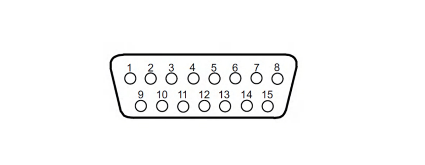
Pin Definition
DB15 Pin definition explaination
|
PIN |
1 |
2 |
3 |
4 |
5 |
6 |
7 |
8 |
|
Definition |
Sin+ |
Sin- |
Cos+ |
Cos- |
Index+ |
Index- |
/ |
HV- |
|
PIN |
9 |
10 |
11 |
12 |
13 |
14 |
15 |
|
|
Definition |
GND |
Vs |
GND |
Vs |
/ |
/ |
HV+ |
|